Someone asked me how to make a honeycomb grid in @FreeCADNews. Here's how I do it, and bonus it's parametric! ⬇️
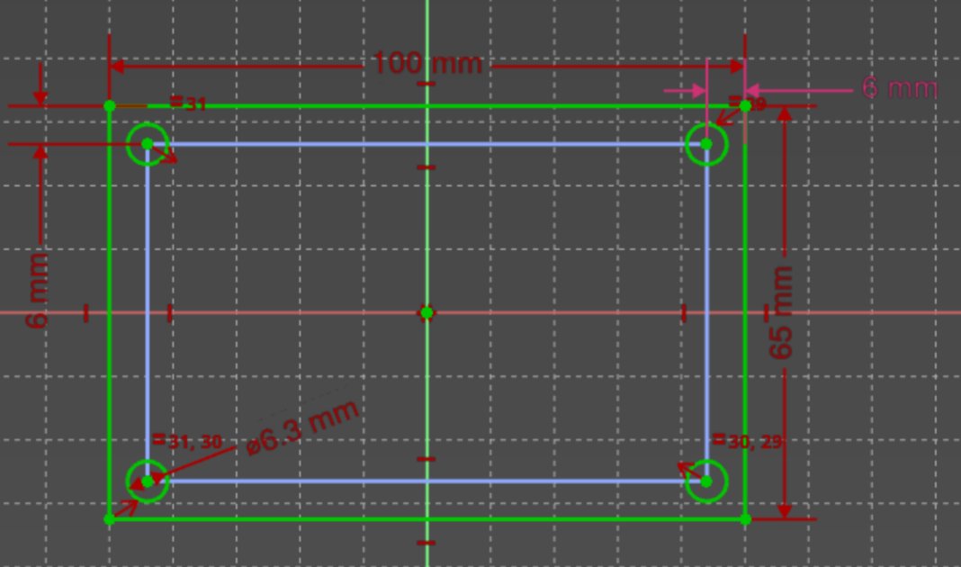
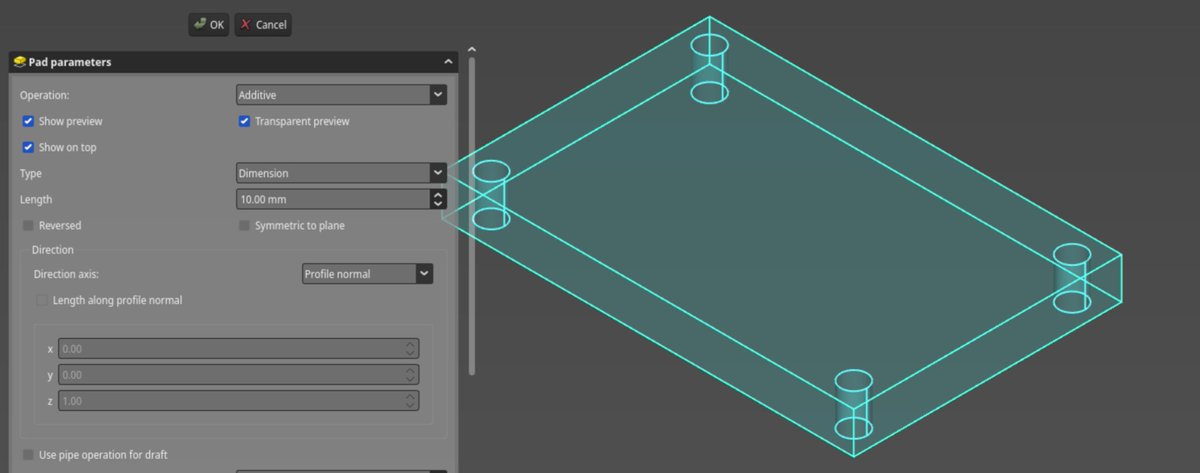
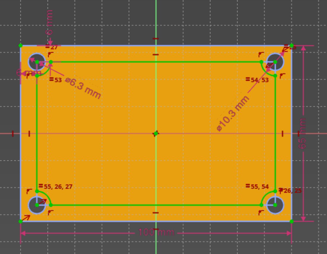
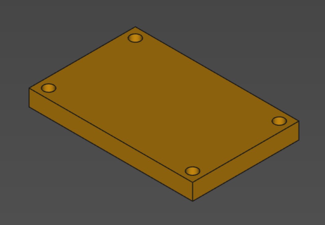
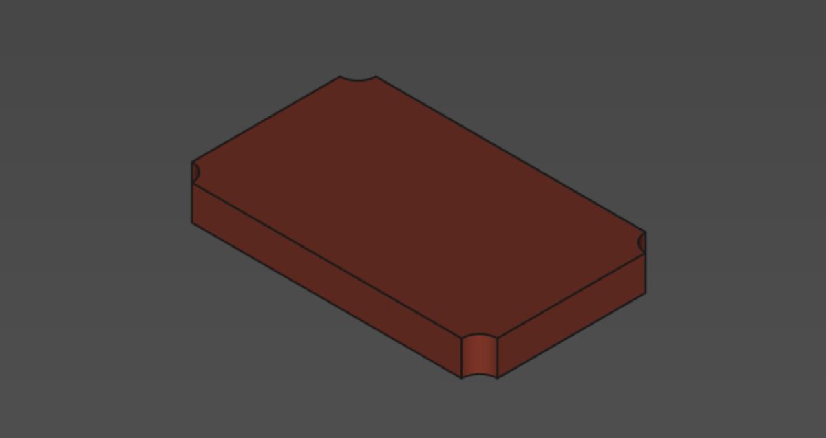
Let's start with a simple plate with four holes. I give a name to each dimension in the sketcher so that I can re-use them later.
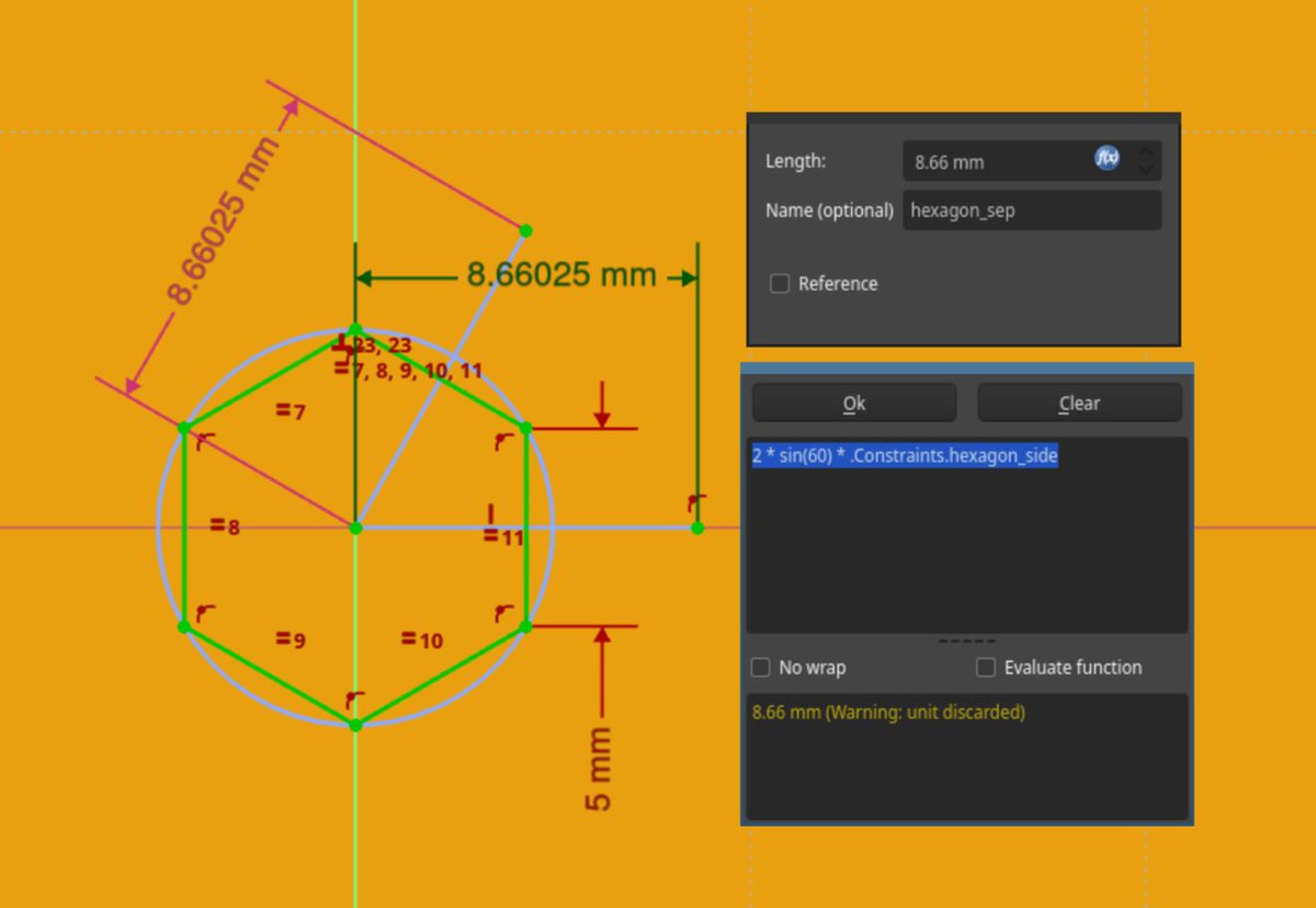
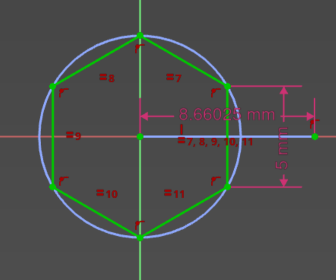
Then I create a new body and start sketching on the XY plane. For this example I wanted to constrain the hexagon side, so a bit of trigonometry is needed to get the width of each hexagon. I also decided here that the separation between hexagons would be about 2mm.
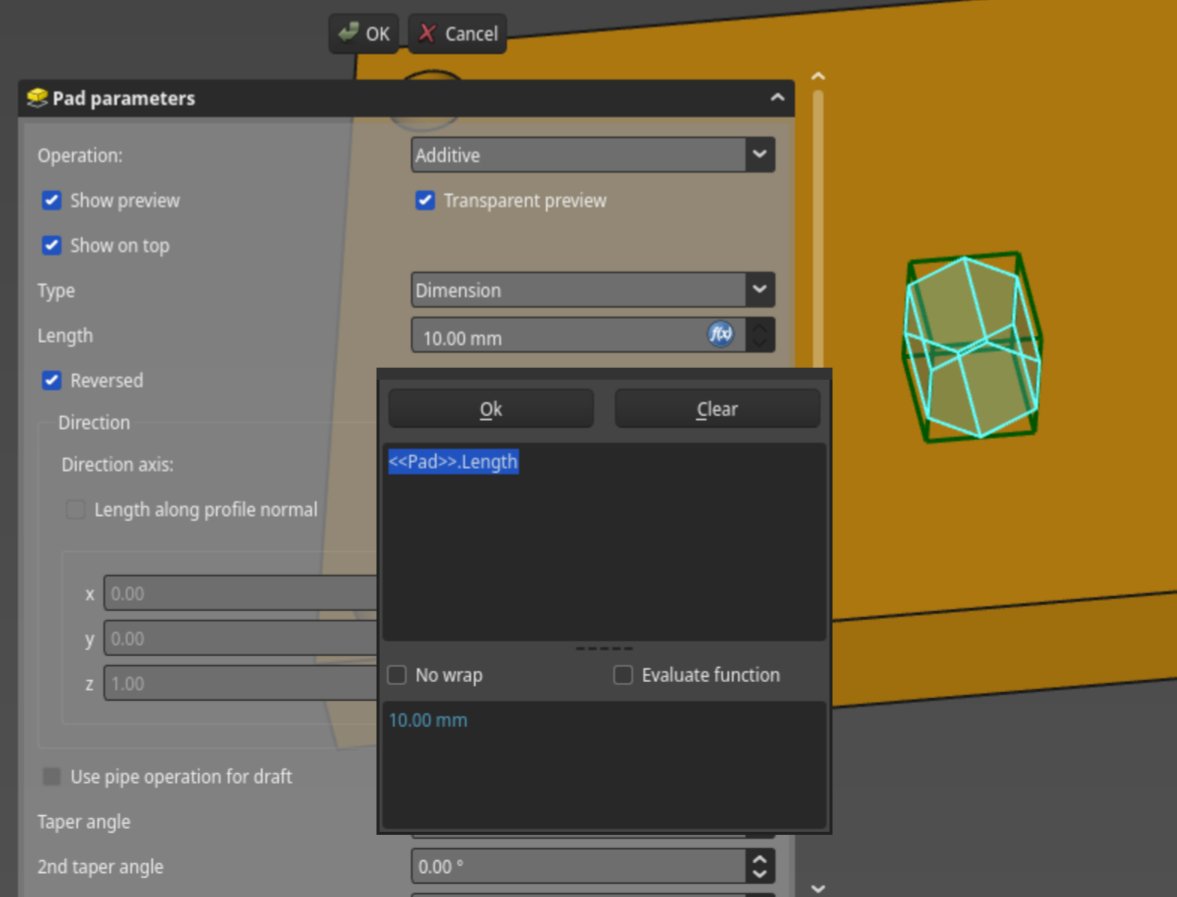
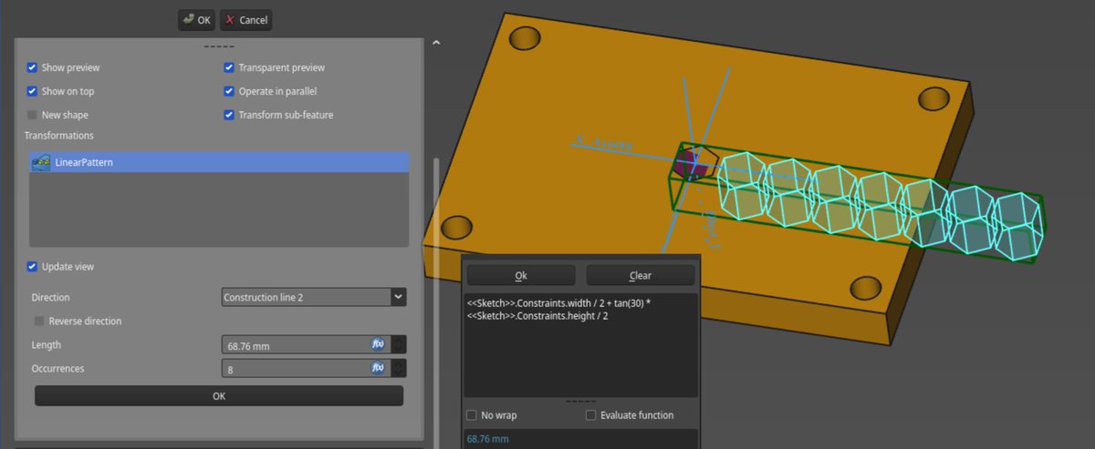
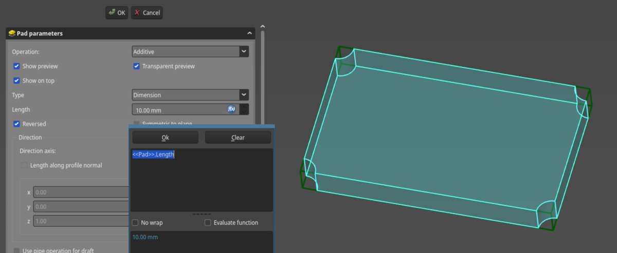
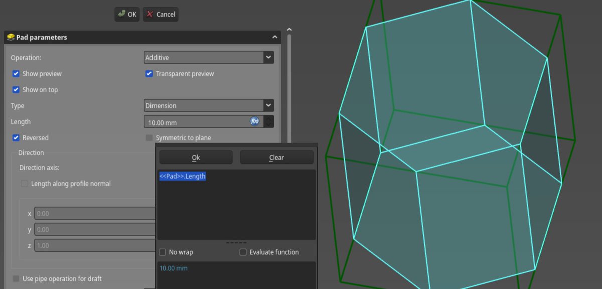
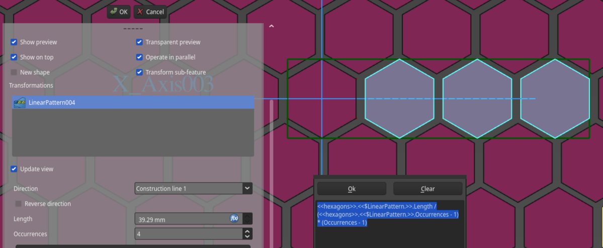
The two construction lines will serve as directions to which we repeat the hexagon. Notice how I also link the pad length of the new solid with the plate pad length. Then we head to the Create MultiTransform tool in Part Design, and start a first LinearPattern. We need it a bit longer than the width of the plate since we will duplicate the hexagons sideways. Any "big" number will do, but a bit of trigonometry gives me the exact length.
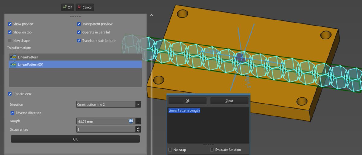
Then using another LinearPattern I can complete the line of hexagons. Since our pattern is symmetric I could also have used a symmetry tool. As before I use one of the construction lines for the direction of the pattern.
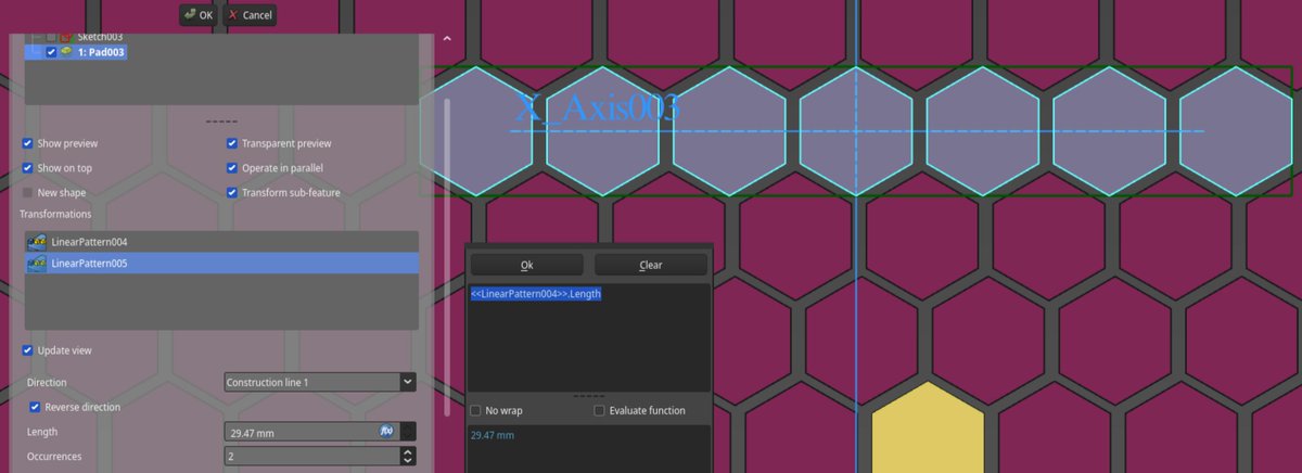
Now I do the other direction! Using another LinearPattern, the second construction line, and a bit of trigonometry (again).
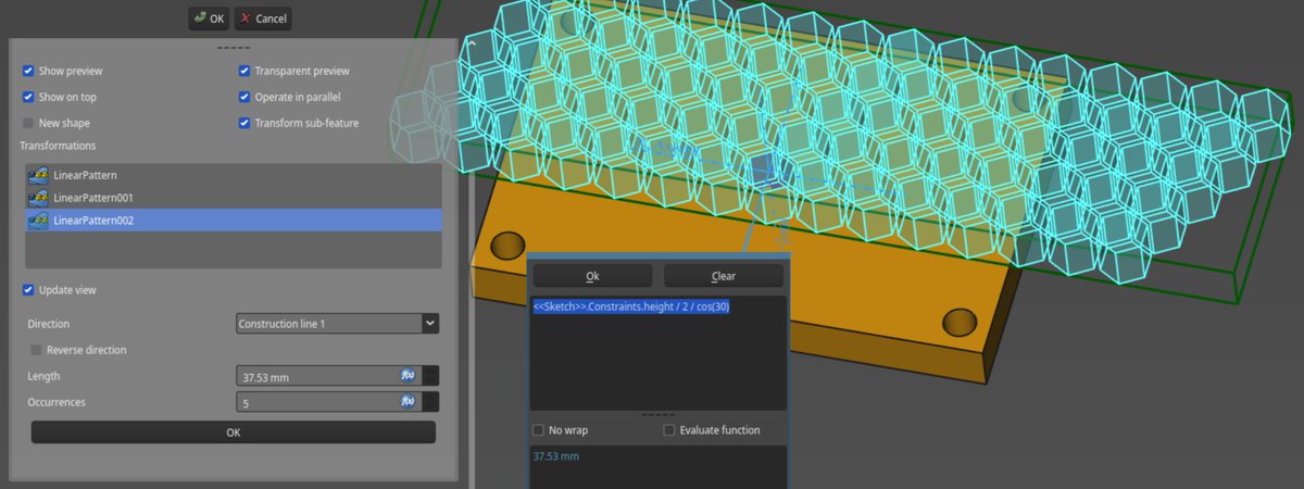
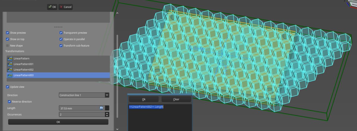
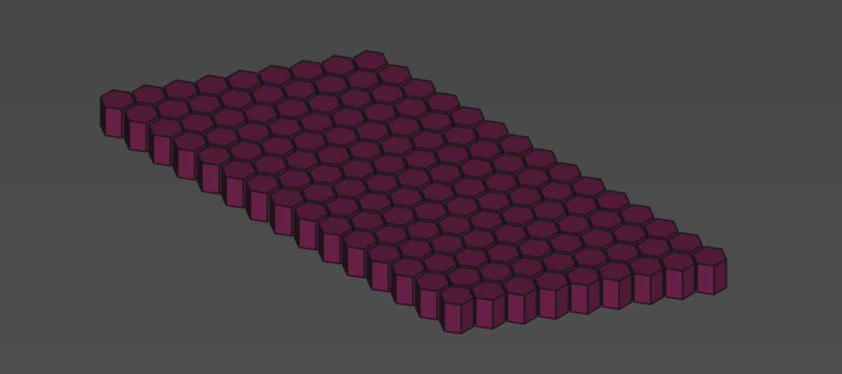
The number of occurrences is given by Length / <<Sketch001>>.hexagon_sep . Freecad will round that to the nearest integer, if you're not happy with that, you can mess around with ceil and floor. Then, once again I can complete the pattern.
Let's create another body using the sketcher. It will represent the area where I want the honeycomb pattern to be present. I can re-use the dimensions I set for the base plate using their name.
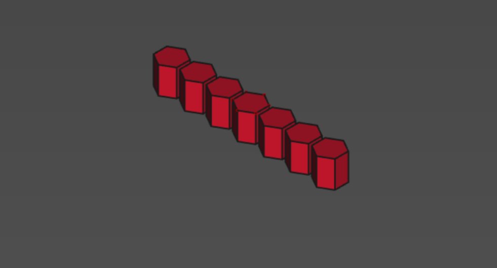
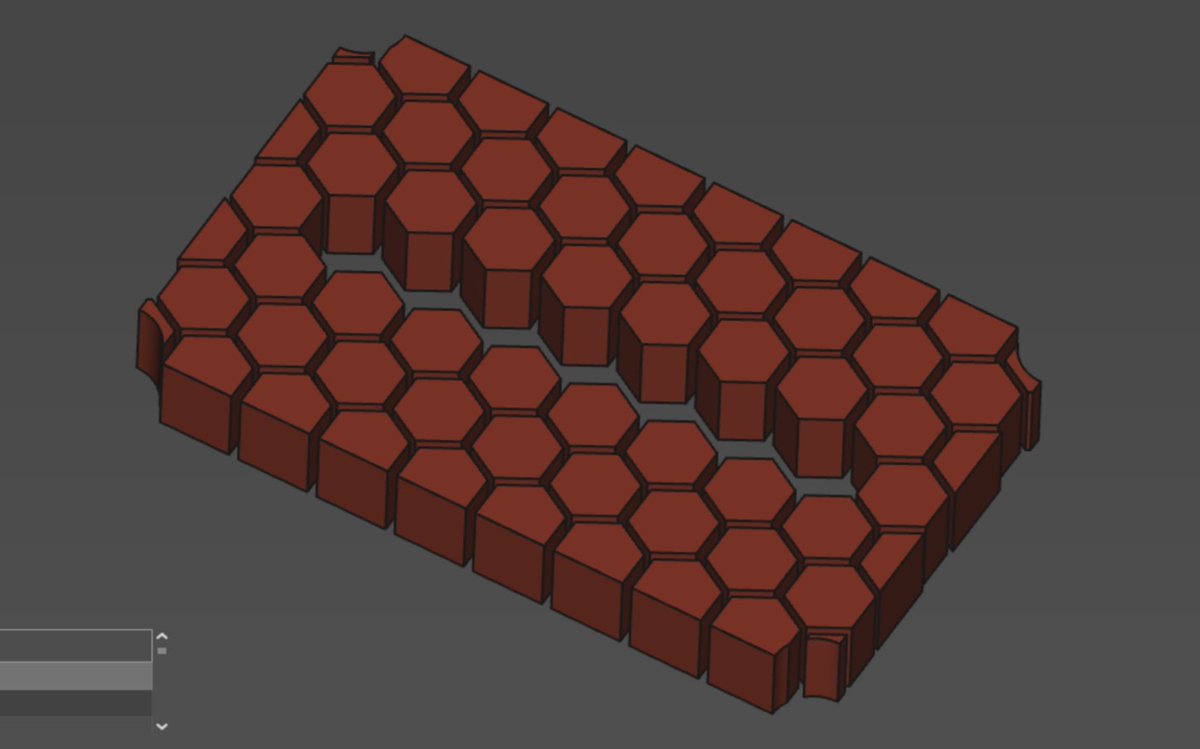
One body remaining! We want some of the hexagons to be full. So let's create a body representing these. It re-uses the dimensions of the first hexagon.
Now I want to repeat the body a certain amount of time to fill some of the hexagons. Once again MultiTransform is our friend.
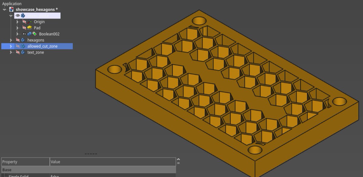
Notice that I used the dimension from the honeycomb pattern to match the correct positions of the hexagon. Also, everything being parametric, I can simply change the number of hexagons by setting the Occurrences parameter of LinearPatter004. At this stage, I have four bodies. I named them main_plate, hexagons, allowed_cut_zone and text_zone. Let's combine them cleverly using boolean operations!
First, let's remove the text zone from the allowed cut, using PartDesign's boolean operation.
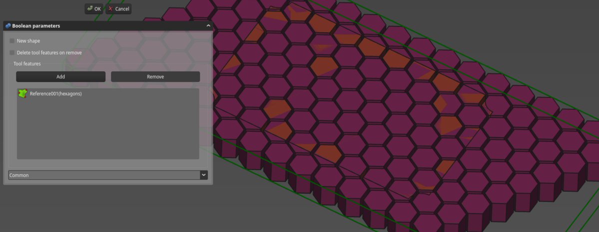
Then I can create the cut zone, which is the intersection between the allowed cut zone and the hexagons.
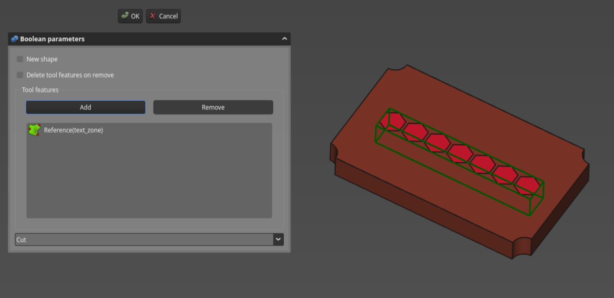
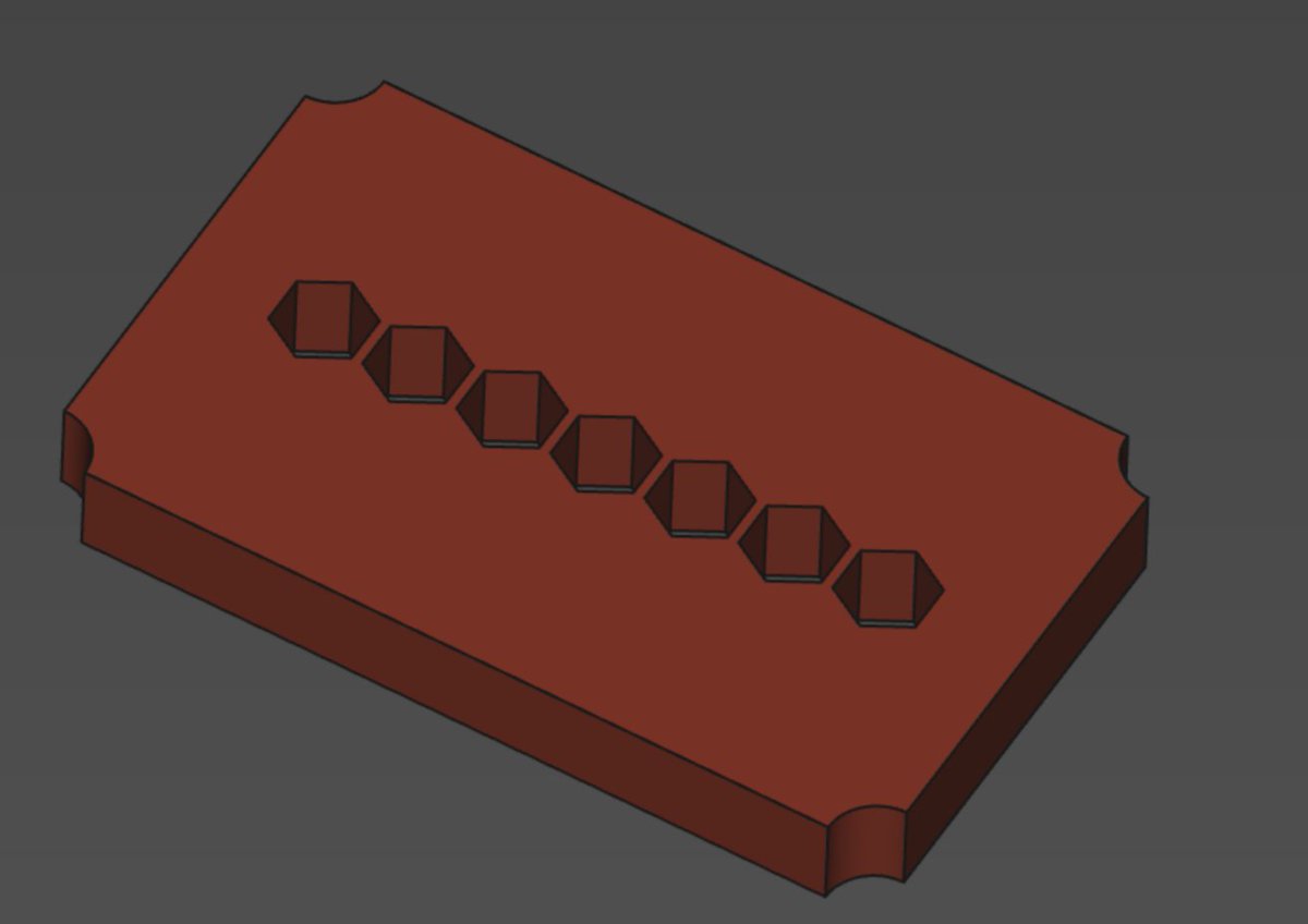
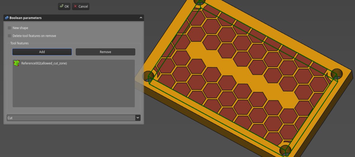
Finally, I can do the cutting, by taking the difference between the base plate and the cut zone.
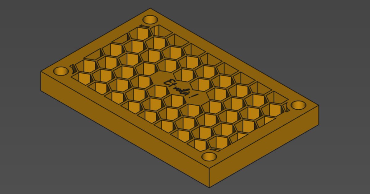
I just need to add some text using the Draft workbench... whoops, the text zone is a bit too big, good thing that our model is parametric, so we can easily change its size. 😬
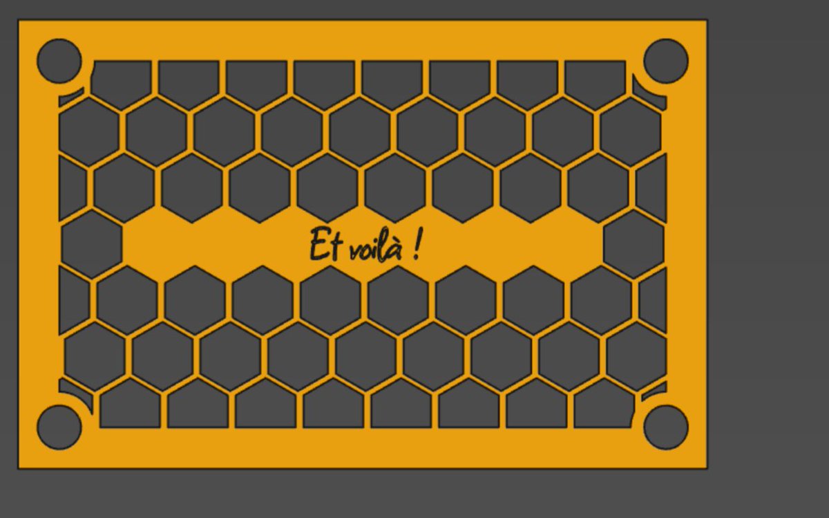
And there you have it!
If you want to mess around with the model, it is available here.
Have fun!